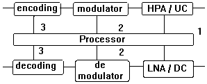
 Figure 1. Sequential Algorithm for FCM
ELEKTRO INDONESIA Edisi ke Sepuluh, November 1997
In addressing to first question, works have been done previously [Gremont et al, 96][ Filip & Vilar, 90], but its adoption to the 'big' system involving multi-beam operations seems necessary to be exercised. In particular, such a requirement is even more so if we were to develop a KaSS which shall serve as bridges and routers of different economic regions spanning from the highly northerned areas all the way down to the tropical regions, a system like Asia Sky-Link [Nugroho & Priyanto, 96].
With the objective in mind of solving the Asia Sky-Link, the present work that has been carried out consists of the following :
Throughput = K.Symb. Rc, provided that
Pb ( Eb/No, Symb, Rc ) < Pb-threshold
with the constraint of P < Pmax; Symb < Symbmax; and Rc
< Rcmax.
Here P and Pmax is in watts, Symb is equal to parameter m in the
term of m-ary modulation, whereas Rc and Rcmax represents coding
rates.
Instead of formulating the complex multi-dimensional algorithm, we prefer to adopt sequential method so as to reduce complexity. Simply, the sequential algorithm says, if any deviation from clear sky prevails , power control will apply all the way up to maximum Pmax being reached; (in such a case there will be no change of Pb); should further deviation continues to happen, symbol control shall then apply up until maximum Symbmax being reached; should again further deviation prevails, now the algorithm to search for (quantumly preconditioned) coding rate increase to be made. Should the Pb-threshold can not be achieved, quantum jump to other smaller Symb is to be made by exerting the best efforts to maximize throughput within the constellation chosen.
Diagramatically, the method can be depicted as follows (Fig. 1).
 Figure 1. Sequential Algorithm for FCM
This sequential algorithm is analised using BPSK, QPSK and 16 QAM modulation , in which each of those modulators also equiped with viterbi-decoded convolutional forward error correction (FEC- K=7, R= Ω, 1/3). Each type of FEC will contribute coding gain as follow [Roger L.Freeman,1991] :
K=7, R=1/2, coding gain = 3.1 dB The Pb curves as a function of Eb/No with
constellation as parameters is depicted in figure 2.
K=7, R=1/3, coding gain = 3.6 dB
For the purpose of clarrifying the principle of bit
error probability for each type of modulator, following [Ziemer, 1991]
is repeated here :
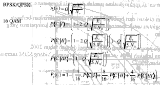
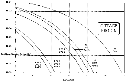
Figure 2 : Pe vs. Eb/No in BPSK/QPSK – 16 QAM
Suppose that we are given Pb-threshold = 10-6. Disposing the instantaneous operating point at point A (Pb1, Eb/No1, Symb1, Rc1). Now there will be a fading encountered, and by prediction process the feedback mechanism can compensate for the Pb degradation by boosting up the HPA's Earth Station Power, so as to slide the operating point back to its original position (Figure 3).
Henceforth, as long as the Pmax is not exceeded, there will virtually be no performance degradation, since the control process will send back the sliding operating point to the original position along the Pb curve path. Suppose that Pmax is about to be exeeded, and let the Pb-threshold is also exeeded.
The next effort would be to let the operating point jump vertically downward till another constellation curve is intersectioned. Presuming that by residing to this very point Pb-threshold is achieved, then temporarily the link can dwell in this constellation, otherwise a quantum leap to the other constellation family can be initiated (Figure 4). And so forth.
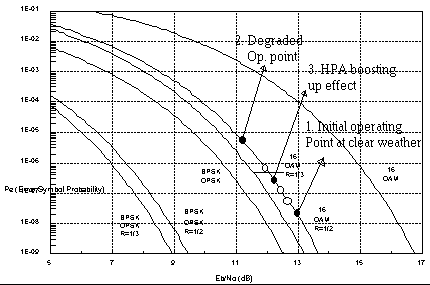
Figure 3 : Ilustration of HPA boosting up effect.
: various position of the Operating point after HPA boosting
( no performance degradation )
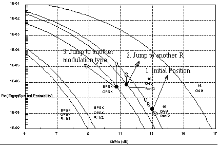
Figure 4. : Ilustration of operating point downward vertical jumping
The Monte Carlo simulation for such an algorithm is shown in the Figure 5, and comparison with the uncontrolled attenuated link showed the performance improvement of Sequential Algorithm, stipulated in Table 1.
It is now to explain the tasks to be carried out by the processor:
Prediction by using ARMR process is shown in Figure 6.
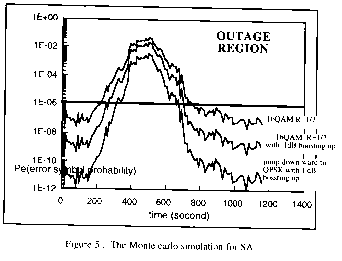
Figure 5 : The Monte carlo simulation for SA
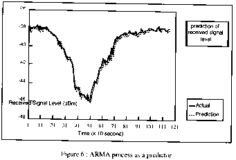
Figure 6 : ARMA process as a predictor
|
OUTAGE PERCENTAGE (%) |
|||||||||
|
using Sequential Algorithm ( SA ) |
|||||||||
|
without |
BOOSTING UP POWER |
||||||||
|
SA |
1 dB |
2 dB |
3 dB |
||||||
|
16 QAM R=1/2 |
QPSK |
16 QAM R=1/2 |
QPSK |
16 QAM R=1/2 |
QPSK |
||||
|
46.6 % |
38.8 % |
30.2 % |
32.8 % |
20.7 % |
22.4 % |
17.2 % |
|||
Table 1 : Performance improvement of SA
Now, as regard with the satellite power dynamics, some stringent assessment would be necessary in view of the boundedness of satellite power availability. However, reduction factors of the whole aggregate power dynamics trickle from the fact that a) there will be less probable that rain precipitations prevail to the whole beams, b) there will be more beam areas which undergo less severe rain attenuation, c) it is more true if we are dealing with pencil beams distantly separated such that the rain phenomena will be less and less correlated. In other word, suppose that the number of beam is N, the satellite power dynamics will certainly be of N.Psmax.K, where K << 1.
Expanding the use of the present algorithm onto the true multi-beam KaSS, represents somewhat involved method. The analysis follows. First, let us assume that there is a strong statistical correlation between any link within any single beam. This is particularly true when we further note that the diameter of such a beam at the earth surface will be in the order of less than 500 Km, and will be more true as the figure diminishes to several scores of km. The consequence of this would be that the ARMA process of each beam can very well be represented by any of such a process resulting from identification effort from th`e associated (measurement) data from the the beam. Second, in certain percentage of time especially when severe fading prevails at some big number of beams, the downlink compensation might result to excessive PA power thereby imposing higher thermal, mass-budget problem to satellite design. Therefore, in such a case the inverted sequential algorithm can be called for, namely, instead of controling PA power at the first place, we should rather propose a symbol control first, followed by a coding rate control, and finally a power control, to mitigate the fade due to the rain attenuation time series. beam. For the purpose of adaptive control system one can now predict the time series within k-step order , and using such a random variable to run the SA.
6)
The practical ways of implementing the the algorithm to multi-beam KaSS, would be as follows:- the ARMA coefficient can be downloaded by the common signalling band from NCC to any particular VSAT.
- any receive signal (which is a beacon signal) will give an information to the prediction process; this information shall be resent to the satellite for a command of downlink signal
- the predicted time-series will drive uplink compensator at the uplink direction
- soon as Pmax is achieved, every individual shall carry out algorithm set forth in the item no 4) above.
- in this analysis it is assumed that beams which are farly located are statistically independent so that any link incorporating the two beams will have independent fading period such that it is reasonable to assume that rain degradation will be either at the uplink or at the downlink only, but not both at the same time. On the other hand, any connection involves only one beam, in such a case double control is unavoidable. This requirement shall eventually be taken into account into the whole design process of the spacecraft. See athe analysis in the number 5 above.
7) Performance measurement can be proposed using the following assessment: It is assumed that the system will be at the so called normal operating region when Pb< Pbthreshold. Therefore, performance parameter , such as the availability, can be easily defined as the percentage of time that the system (link) dwells at the region. We have to note that, during such a dwelling time, the power compensation has taken effect; in effect, the whole algorithm will affect the whole performance, and the only way to measure this performance is to compare with the uncompensated system performance. The algorithm behaves as a transformation machine which improve the statistical characteristics of the whole system, under the presence of the rain degradation. The improvement factor is simulated against the dynamics factors of uplink and downlink powers. See figure 7.
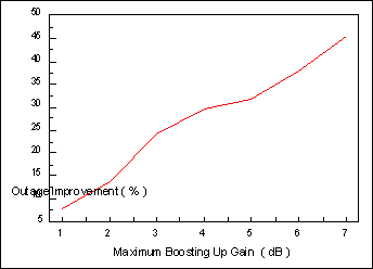
Figure 7. : Improvement factor chart